Built for spindle speed control
This spindle inverter range is intended for engraving machines and CNC routers that require stable high-speed output, clean acceleration control, and practical cabinet integration.
Companion drive / spindle control
A dedicated spindle inverter range for engraving machines and CNC routers. 220V versions run at 1000 Hz as standard, with 1200 Hz custom builds for 220V 8-pole ATC spindle motors; 380V versions run at 3000 Hz.
220V output frequency
1000 Hz standard
1200 Hz is custom-built for 220V 8-pole ATC spindle motors
380V output frequency
3000 Hz standard
Configured for 380V ATC spindle motor applications
Signal path
0-10V / 0-20mA / RS485
Useful for router controllers and retrofit cabinets
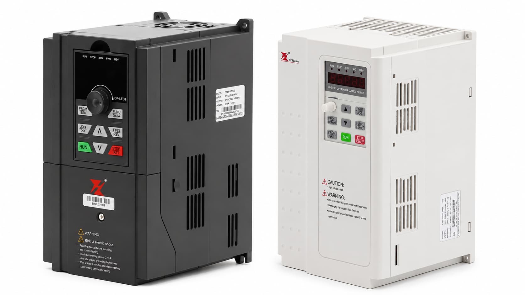
Enclosure voltage views
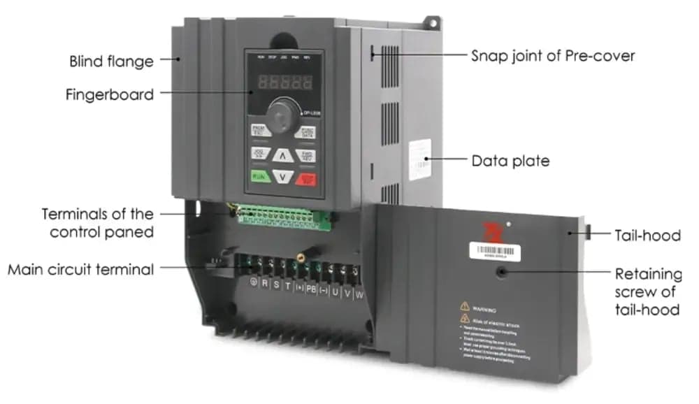
White enclosure is 220V, black enclosure is 380V
Input
1AC 220V / 3AC 220V / 3AC 380V
Output
220V: 1000 Hz / 380V: 3000 Hz
Power range
3.7-11 kW
Control
V/F, PID, RS485
Protection
Overcurrent, overvoltage, overload
Selection logic
This range is built for spindle applications that need stable speed control, cabinet-side wiring flexibility, and dependable protection in day-to-day production.
This spindle inverter range is intended for engraving machines and CNC routers that require stable high-speed output, clean acceleration control, and practical cabinet integration.
The inverter manages speed through keypad, terminal, digital I/O, analog signal, multi-step speed, PID, and RS485 for both new router cabinets and retrofit control systems.
Low-speed torque support includes 150% start torque at 1.5 Hz together with automatic and adjustable torque boost, helping the spindle start and ramp more smoothly under load.
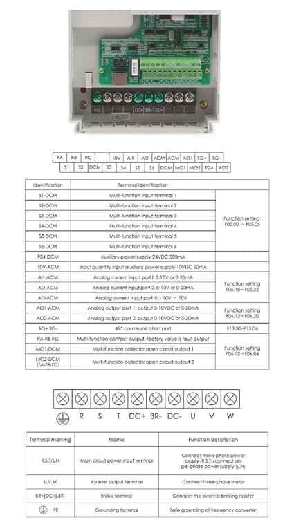
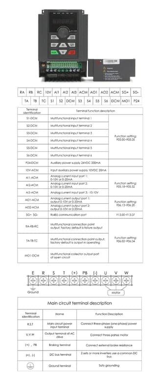
The listed VFD models include 24VDC auxiliary power, 10V reference, multiple multifunction inputs, 0-10V or 0-20mA analog inputs, analog outputs, relay outputs, and RS485.
Structured specs
Review the main electrical specifications, enclosure dimensions, and the available 220V and 380V power and frequency configurations.
Technical standard
Dimensional reference
Use this drawing and table to confirm mounting clearance for the selected VFD model. The listed dimensions apply to both 220V and 380V versions.
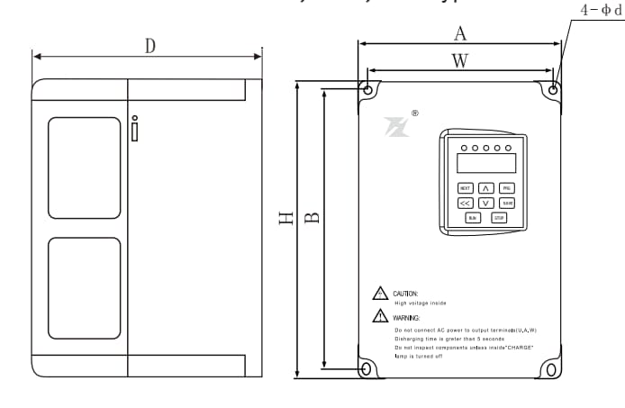
| Power | A (mm) | B (mm) | H (mm) | W (mm) | D (mm) | d (mm) |
|---|---|---|---|---|---|---|
| 3.7 kW | 154 | 238 | 250 | 142 | 155 | 5 |
| 5.5 kW | 154 | 238 | 250 | 142 | 155 | 5 |
| 7.5 kW | 154 | 238 | 250 | 142 | 155 | 5 |
| 11 kW | 205 | 300 | 322 | 190 | 193 | 6.5 |
Available combinations
Compare the four available power levels by supply class. 220V models run at 1000 Hz as standard, while 380V models run at 3000 Hz.
3.7 kW
Standard
5.5 kW
Standard
7.5 kW
Standard
11 kW
Standard
3.7 kW
Standard
5.5 kW
Standard
7.5 kW
Standard
11 kW
Standard
220V frequency requirement
220V models run at 1000 Hz by default. If the inverter will be paired with a 220V 8-pole ATC spindle motor, request the custom 1200 Hz version. This requirement does not apply to 380V models, which run at 3000 Hz as standard.
Control and I/O
These control and I/O functions help the inverter integrate cleanly with motion controllers, cabinet logic, and spindle-side feedback requirements.
The control platform supports keypad operation, analog AI1/AI2/AI3 inputs, multi-speed running, simple PLC logic, PID, RS485 communication, and potentiometer-based frequency selection.
Typical CNC integration uses a 0-10V speed signal through AI or AI1 plus ACM. The listed VFD models support 0-10V or 0-20mA on AI1 and AI2, while AI3 supports -10V to 10V.
Relay outputs, multifunction transistor outputs, and analog outputs are provided for run status, frequency-level detection, zero-speed state, and other machine-side logic.
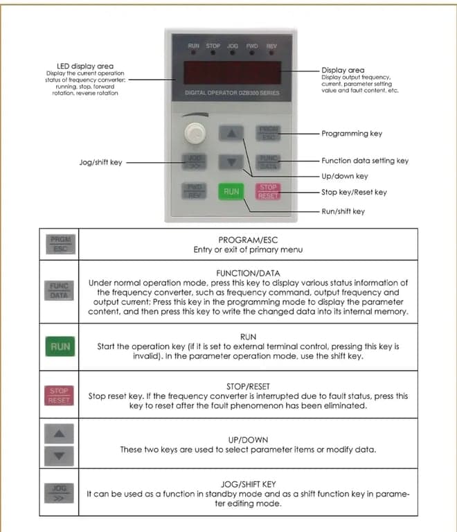
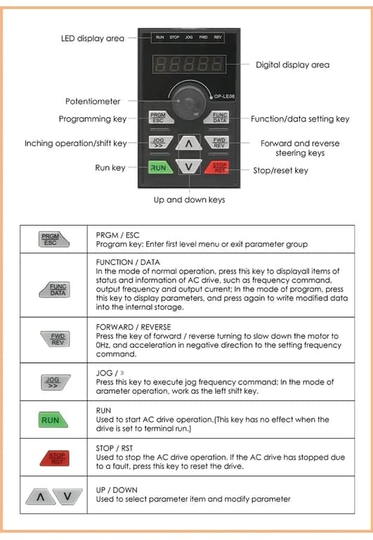
The keypad interface provides access to setting frequency, output frequency, output current, output voltage, and bus voltage, which is useful during startup and tuning.
Application fit
This inverter family is more useful when the buyer is matching it to a spindle package, cabinet logic, and target process window instead of choosing only by headline power.
Scenario 01
ATC router spindles that need an inverter matched to spindle power, supply class, and target speed range.
Scenario 02
Engraving machines and CNC retrofit cabinets that use 0-10V analog speed command from the motion-control board.
Scenario 03
Spindle packages that need multi-segment speed, PID support, relay feedback, or RS485 integration rather than a bare minimum standalone drive.
ATC spindle motor example
This example uses a 3.7 kW, 220V, 1200 Hz custom VFD inverter with a 3.5 kW, 220V, 8-pole, 18000 RPM ATC spindle motor. Confirm the final nameplates before entering any values.
Parameter values
| Function code | Manual function | Example setting | Why it is set this way |
|---|---|---|---|
| F00.03 | Maximum output frequency | 1200 Hz | Sets the inverter's maximum output frequency for this custom high-speed spindle configuration. |
| F00.04 | Run frequency upper limit | 1200 Hz | Allows the running command to use the full 1200 Hz limit set by F00.03. |
| F02.02 | Motor rated frequency | 400 Hz | Defines the 400 Hz base point for the 8-pole spindle motor's rated data. |
| F02.03 | Motor rated speed | 6000 RPM | Defines the 6000 RPM rated-speed base point at 400 Hz for the 8-pole spindle motor. |
| F02.04 | Motor rated voltage | 220 V | Matches the motor rated-voltage setting to the 220V ATC spindle motor nameplate. |
How the values work together
For an 8-pole motor, 400 Hz corresponds to a 6000 RPM synchronous-speed base point. Setting F00.03 and F00.04 to 1200 Hz extends the available frequency limit to the 18000 RPM target for this spindle. F02.02 and F02.03 define the motor's rated base data; F00.03 and F00.04 define the permitted maximum operating frequency.
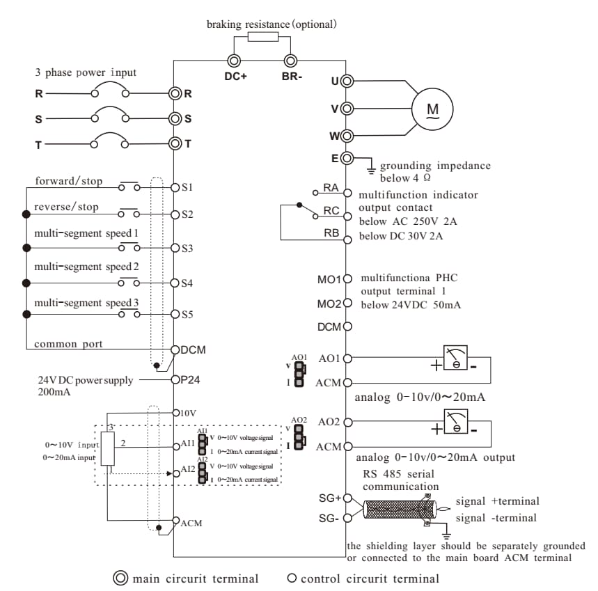
Wiring reference
Use this reference when planning incoming power, spindle motor output, braking resistance, control inputs, analog signals, relay outputs, and RS485 communication.
Installation
These installation points help protect the inverter, keep cooling effective, and reduce commissioning issues during first power-up.
Confirm the incoming supply matches the inverter nameplate before energizing. Incorrect supply voltage can damage the drive.
Never connect the input power supply directly to U, V, W. Those are motor output terminals.
Confirm the spindle motor and inverter are compatible before the first start to avoid motor damage and nuisance protection trips.
The installation diagram shows at least 100 mm clearance above and below the drive so cabinet heat can escape.
Where metal dust is present, use radiator-outside-cabinet installation and a sealed electrical enclosure with enough internal volume.
For models with braking resistor terminals, connect the resistor only to the specified brake terminals, not arbitrarily across the DC bus.
Motor matching
A spindle inverter is only as stable as the motor data and field conditions it is commissioned against.
The standard adaptive motor is a four-pole squirrel-cage asynchronous motor. If the application uses a different motor type, selection should be based on rated motor current.
If a non-variable-frequency motor is used, cooling effectiveness drops as spindle speed drops. For hot-running duty, add forced ventilation or choose a motor intended for variable-frequency service.
Motor insulation testing should be done with the motor leads disconnected from the inverter. Use a 500V insulation tester and keep insulation resistance at or above 5 megaohms.
If contactors are installed at the inverter input, they should not be used as the normal start-stop method. Frequent charge-discharge cycles shorten capacitor life.
Commissioning
Use these startup steps to match output limits, command source, and protection values to the actual spindle package.
Protection
These protection functions help reduce downtime, protect the spindle package, and simplify fault diagnosis on the machine side.
Brake resistor matching
These published values are useful when the spindle has fast deceleration demand or the cabinet needs a defined braking hardware path.
| Supply | Inverter power | Resistor power | Resistance |
|---|---|---|---|
| 220V | 3.7 kW | 400 W | 68 ohm |
| 220V | 5.5 kW | 400 W | 30 ohm |
| 220V | 7.5 kW | 400 W | 30 ohm |
| 380V | 3.7 kW | 400 W | 100 ohm |
| 380V | 5.5 kW | 750 W | 75 ohm |
| 380V | 7.5 kW | 1000 W | 60 ohm |
| 380V | 11 kW | 1500 W | 40 ohm |
Operating envelope
These constraints should be checked at the cabinet level before the spindle and inverter package is frozen.
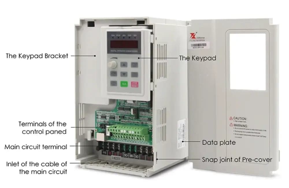
Reference views
These images help buyers review enclosure style, interface layout, and overall product presentation before cabinet integration.
Matched package quote
Share your ATC spindle motor details—holder, power, pole count, target speed, voltage, cooling, and controller signal. We will confirm a compatible VFD inverter and quote the spindle-and-drive package as one matched system.
Spindle
Holder, power, pole count, and target speed
VFD
Supply class, output frequency, and control signal
Package
ATC spindle motor + matched VFD inverter
Delivery
Quantity, lead time, and destination country
Quotation workflow
Confirm the ATC spindle motor data
Review the holder, power, pole count, target speed, cooling method, and machine duty.
Match the VFD electrical setup
Confirm supply class, output frequency, control signal, and wiring requirements for the selected spindle.
Quote the complete matched package
Return the recommended ATC spindle motor and VFD inverter package with production and delivery details.
Your request starts with the ATC spindle motor and VFD inverter as one matched electrical package.